Designing an Ergo Keyboard (with Haskell and OpenSCAD)
YAK: A Keyboard
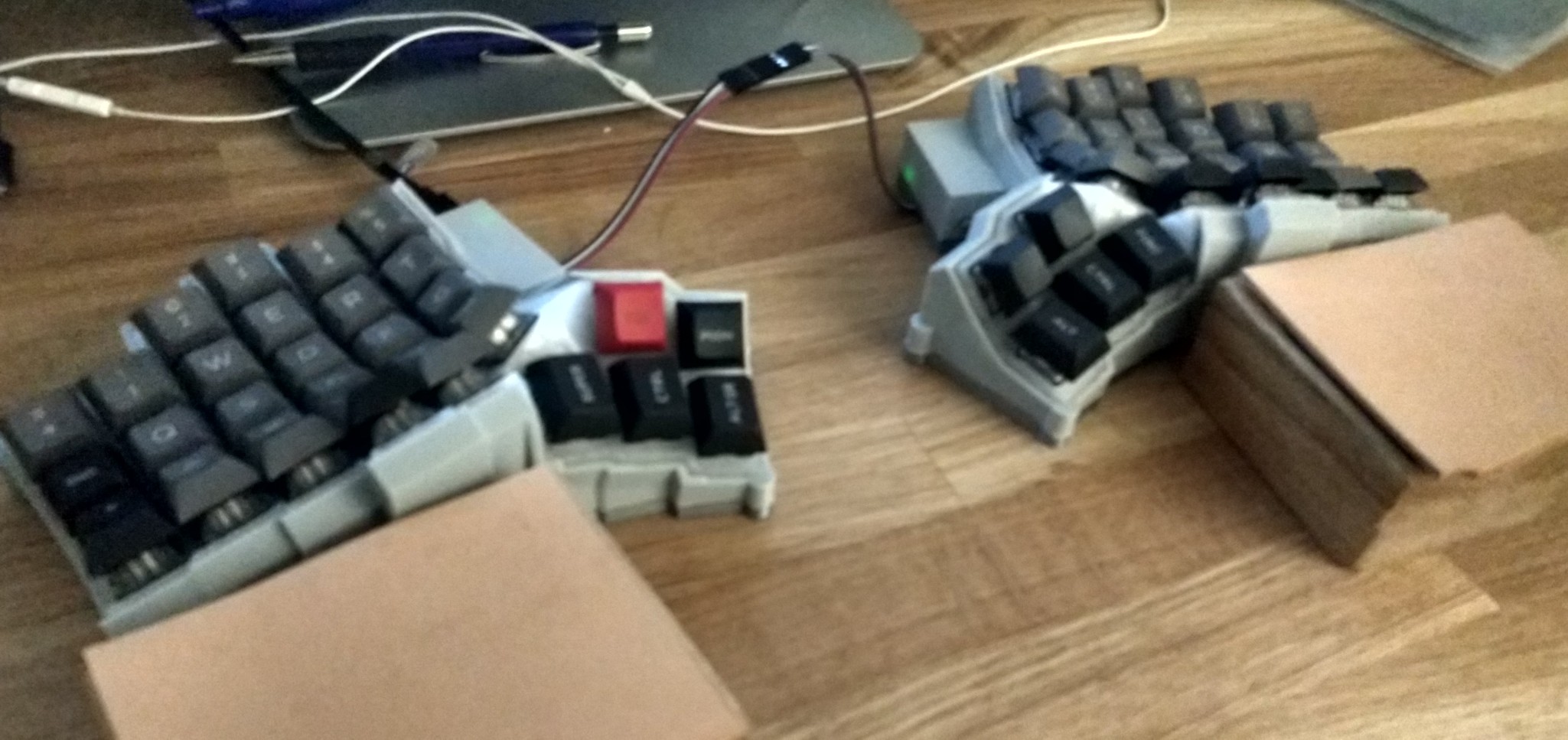
In an insanity period I decided that it was a good idea to design and build my own keyboard. More about the goals here. In this post I’ll give a glimpse of the design process and technologies involved.
The technology
Of course I won’t be designing a keyboard in a WISIWIG CAD software (I don’t have enough sanity points remaining for that). Rather I want to program my desired constraints and let the machine do the rest. Fortunately we have OpenSCAD for that. However it’s rather limited in its expressive capabilities, so I have layered a Haskell interface on top of it. (There is a “closure” program and library that I could have reused, but reading other people’s code is not my idea of fun. Plus, no types?!) Without going into too many details (I’ll give a complete course on another occasion), I am using types to track the relevant anchor points of shapes. Here is an example function to give a flavor of how to use it:
corners :: HasCardinals xs
        => Part2 xs R -> (Int -> Int -> Option (Part3 ModelPoints R))
        -> Int -> Int -> Option (Part3 ('["bottom"] : '["top"] : xs) R)
corners shape f i' j' = corner <$> f (i' `div` 2) (j' `div` 2)
  where relloc :: forall v xs. HasCardinals xs => RelLoc xs v R
        relloc = cornerRelloc i' j'
        loc x = Loc {locPoint = locPoint (relloc x)
                    ,locBase = locBase (zenith x)} -- direction is the same as original
        corner x = withBase (loc x) (extrude (thickness x) (center relloc shape))
This function is a corner-post creating function that we’ll use below. It extrudes a post, with a given base shape, at each of the corner of a part (for each position in a grid). Of note is the addition of top and bottom anchors in the output type, meaning that we can refer to the top and bottom of the post we created.
An Ergo design
I wanted to design a split keyboard. This means a freer, more comfortable placement of the hands– and having to deal with smaller part. Placing ergonomy first, the next design decision is to find where to place the keys. I am assuming a relatively conventional touch-typing situation where each finger is taking care of pressing keys in a given column. (With the exception of thumbs which have may have several). Then there are several things to consider:
- The curvature of the column.
- Offset of the columns.
- Individual pitch, roll and (even yaw) of each key.
- How many rows should we have (per column)
Let’s discuss the four fingers first.
- I have decided to use a (positive?) curve. This basically
matches the general grasping action of the hand, and I have had good experience with such keyboards in the past. I have used shorter radii for shorter fingers, using a mix of guessing, measuring and prototyping.
I found that offsetting the columns is essential to maximize the reach of fingers. (I want to have as many keys as can be easily accessed.) When stretched out, the fingers have different reaches, and it is on this basis that the rows are staggered.
The pitch of the digit (top?) row is low (almost flat), because the key pushing action happen in this direction. The rest of the curve increases the (forward) pitch of each key. I have even added a few degrees of forward pitch. This has a double effect: (a) it aligns (more) the keypresses with the grasping action. (b) it makes it easier to feel the limit between each row.
I have added a bit of outward roll to the additional index finger column. I have also experimented with inward roll for the additional pinky row, but this did not work out. Indeed the pushing action seems to be directed in a parallel direction for this column.
I have settled down on having a 4-row design, plus a 4-key cluster centered on the middle finger. Even though this is harder to wire, it seems to make best use of the range of each finger.
All these design decisions are captured in the following function. It is parameterized on a generating shape for each key (kModel), and the (i,j) location of the key in the matrix.
fingers :: (Int -> Int -> Part3 xs R) -> Int -> Int -> Option (Part xs V3' R)
fingers kModel i =
  rowBounds $
  fmap (translate (V3 0 (-ofs i) 0) .
        rotate3d (30*degree) xAxis . -- 4 fingers pitch
        translate (V3 (i *^ (dsaWidth+rowSep)) 0 0)) $
  case i of
   0 -> fmap (translate (V3 3 3 0)) $ -- need some extra space
            circularColumnOf (-2*degree) dsaHeight (dsaWidth+rowSep+1.5) (fRadius i) $
            (\j ->
               rotate3d ((-2-3*fromIntegral j)*degree) zAxis $ -- yaw
               relativeTo (V3 (dsaTopWidth/2) 0 0) (rotate3d 0.4 yAxis) $ -- roll
               ki j) -- extra index column
   _ -> circularColumn (fRadius i) ki -- four fingers
  where fRadius 0 = fRadius 1
        fRadius 5 = fRadius 4+1
        fRadius j = fLen j - keyTravel - 20
        fLen :: Int -> R
        fLen 0 = fLen 1
        fLen 1 = 73
        fLen 2 = 83
        fLen 3 = 75
        fLen 4 = 60
        fLen 5 = fLen 4
        fLen _ = error "only 4 fingers"
        rowBounds | i < 0 || i > 5 = const (const None)
                  | i == 0 = limit (homeRow-1) (homeRow+2)
                  | i == 2 = limit (homeRow-3) (homeRow+2) -- wiring this is annoying
                  | i >= 4 = limit (homeRow-1) (homeRow+2)
                  | otherwise = limit (homeRow-2) (homeRow+2)
        ofs i = (fLen 4 - fLen i)
        ki = \j -> intrinsicPitch (-iPitch) (kModel i j)
        iPitch = 7*degree
For thumbs, I tried to make one row activated with downward presses, and one row activated with forward ones. It is even possible to press both keys in a columns simultaneously, which can be useful for (rare) key combinations. The slightly larger keycaps mean that it is possible to activate the keys without feeling the ridge of (spherical) keycaps too much. Cylindrical keycaps would also be an option. A final option would be to use a reverse curvature for the thumb keycaps, like The KeyboardIO model 01, but I am not a fan. (Such keycaps may also be hard to source.)
Here is the less insightful Haskell generator for the thumb cluster:
thumb :: (Int -> Int -> Part3 xs R) -> Int -> Int -> Option (Part xs V3' R)
thumb kModel i j
  | i < 0 = None
  | i > 2 = None
  | j < 0 = None
  | j > 1 = None
  | i == 0 && j == 1 = None
  | otherwise = Yes $
    translate (homeIndexPoint + V3 (-10) (-42) 17) $ -- cluster offset
    rotate3d (-15*degree) yAxis $ -- cluster roll
    rotate3d (15*degree) xAxis $  -- cluster pitch
    rotate3d (15*degree) zAxis $  -- cluster yaw
    (rotate3d ((7*i)*^degree) zAxis) $ -- column yaw
    translate (((-i)*^(dsaWidth+columnSep) - 4) *^ xAxis) $ -- column offset (full)
    (rotate3d ((5*i)*^degree) yAxis) $ -- column roll
    translate (j*^ V3 2 (dsa125Width/2 + dsaWidth/2 - 2.5) 0 ) $ -- row offset
    relativeTo (V3 0 (-dsaWidth/2) 0) (rotate3d ((j*^40)*degree) xAxis) $ -- row pitch
    kModel i j
    where homeIndexPoint = fingerLoc fingers 1 0
Physical constraints
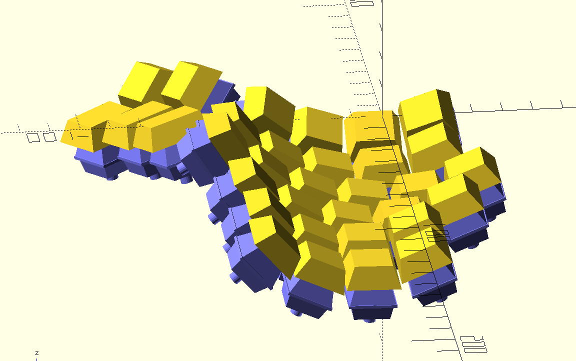
The next thing to do is to measure switches and keycaps. This information can be used to deduce the location of the switches. At this point I have generated a model of keycaps and switches, which allows me to check that keyswitches do not run into each other, and likewise for keycaps, as they are pressed.
The mounting frame
When content with the design, it’s time to build a model of the frame, where the switches will be mounted. This is a pipeline with the following phases:
- place a post at the corner of each switches.
- take the convex hull between at each neighboring 4 such squares
- take the union of all that
- cut out mounts for the switches, and remove any material which would interfere with keycap travels
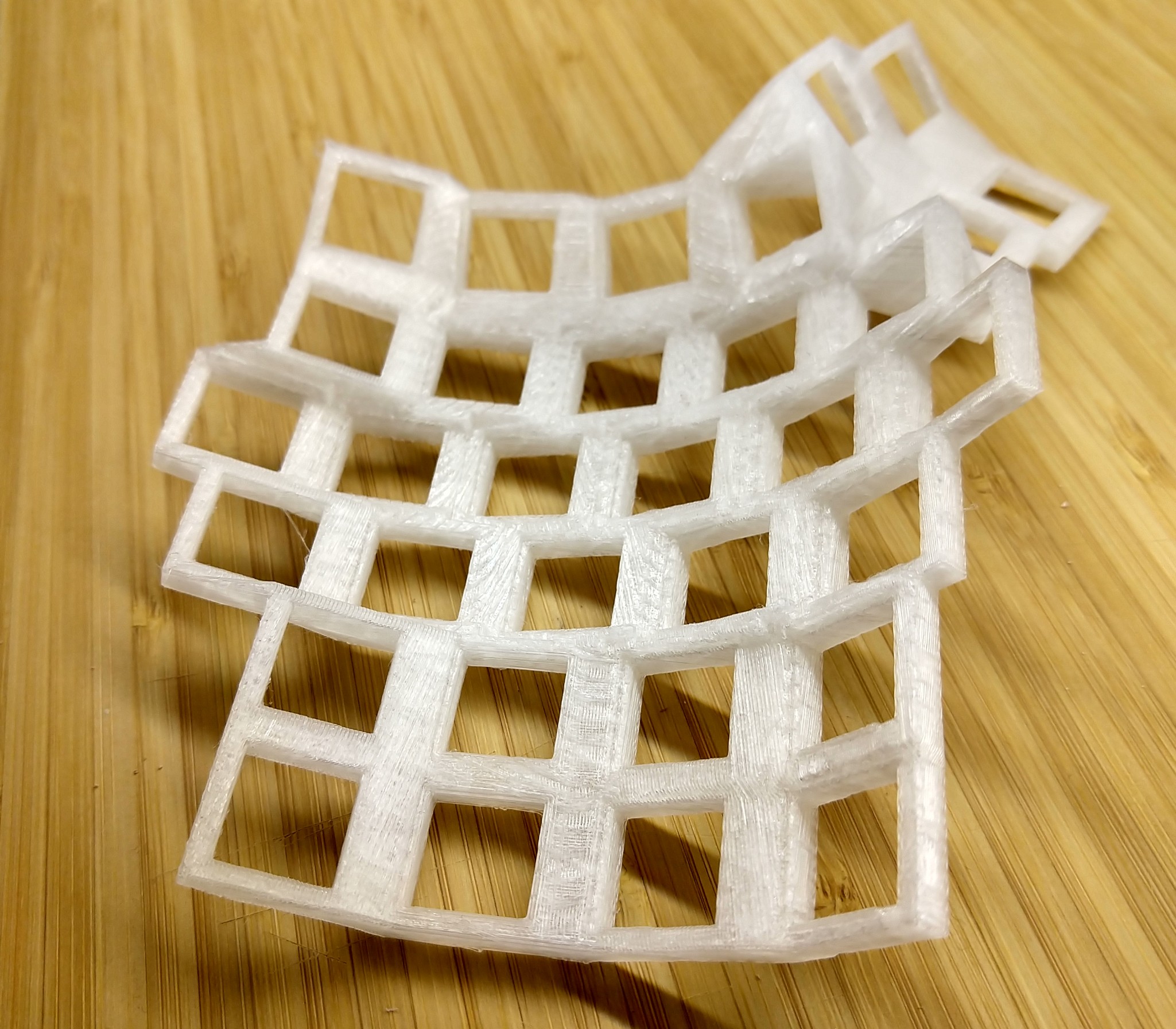
At this stage I have sometimes realized that the frame was not structurally coherent (to many/much holes have been cut). And went back to the drawing board.
frame :: (Int -> Int -> Part3 ModelPoints R) -> Part '[] V3' R
frame base_ = ug (webbing (corners (rectangle $ pure segmentHeight) (hand base_)))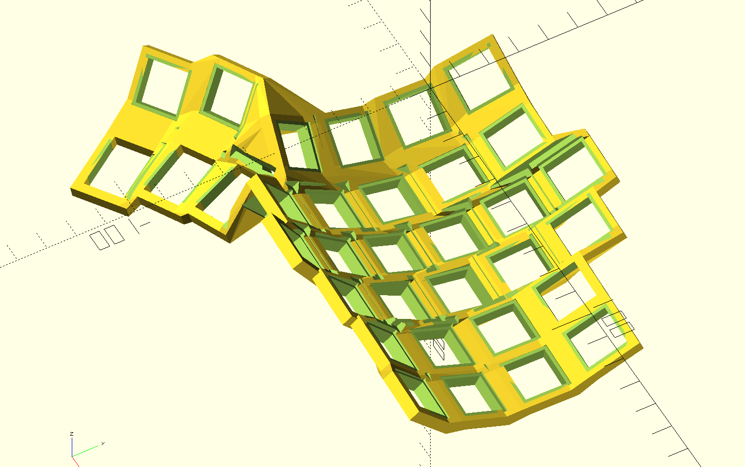
One point about the mounts: the tolerance for the hole will vary with the characteristics of the manufacturing process. (Prototypes to the rescue!)
The rest
What remains is to build an enclosure, so that the frame can rest on something an the electronics (including the microcontroller) are safe from harm. In short, to build the enclosure, the leading principle is to project frame-like objects onto the base plane, and use various boolean operations between such projections. Then you need to figure out where to attach the microcontroller, the ports and how everything attaches together.